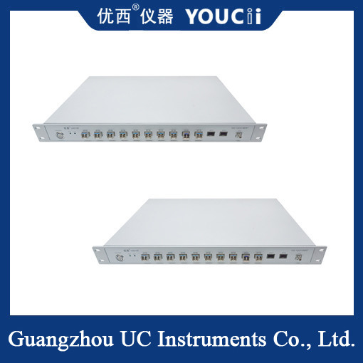
15G 12-Channel Full Rate Optical Error Meter 622M~15.0G BERT
Feature overview
High speed: Data rates up to 15Gbps are supported to meet the test requirements of modern high-speed optical communication systems.
Multi-channel: With 12 optical port channels, all channels can synchronize input and output, can parallel error detection, improve test efficiency.
Full rate test: Support from low speed to high speed full rate error test, covering multiple conventional rate points, suitable for the current conventional active module.
High precision: With low jitter clock output and high-precision error detection capabilities to ensure the accuracy of test results.
12 electrical channels (note that this is an example of an electrical port, and the features of an optical port are similar) : All channels synchronize input and output to enable independent error detection.
Continuous and periodic bit error detection: Provides comprehensive bit error detection.
Support a variety of code types: such as PRBS7, PRBS23, PRBS31, etc., to meet different test needs.
Low jitter clock output: Ensure the stability of the test signal.
Specification
| No. |
Argument |
Min |
Model |
Max |
unit |
| 1 |
Data rate |
0.614 |
0.614,1.22,2.25,2.457,2.5,3.07,3.125,4.915,5.0,6.144,6.25,8.5,9.953,10.00,10.3125,10.52,10.709,11.09,11.32,11.519,11.7 |
11.7 |
Gbps |
| 2 |
Number of channels |
|
12 (12 channel port) |
|
|
| 3 |
Code pattern |
|
PRBS7,PRBS9,PRBS15,PRBS23,PRBS31 |
|
|
| 4 |
Rise and fall time (20% to 80%) |
|
18 |
23 |
ps |
| 5 |
Pattern reversal |
|
Supports signal inversion at the transmitting and receiving ends |
|
|
| 6 |
Signal output amplitude (single-ended) |
200 |
800 |
1000 |
mV |
| 7 |
Data output jitter (RMS) |
|
1.5(10.3125G) |
|
ps |
| 8 |
Data input/output interface |
|
Differential, AC coupling, 50 ohm impedance, SMA |
|
|
| 9 |
Clock output |
100 |
156.25 |
156.25 |
MHz |
| 10 |
Data signal input sensitivity (single-ended) |
|
0.1 |
|
Vpp |
| 11 |
Data output eye map intersections |
50 |
52 |
54 |
% |
| 12 |
Operating temperature |
10 |
25 |
50 |
°C |
Precautions for use
Connection and setting: When using the error meter, the optical communication equipment should be correctly connected to the test, and the appropriate parameters should be set according to the test requirements, such as signal rate, code type, etc.
Monitoring and analysis: After starting the error meter, the number and type of error codes should be closely monitored, and the cause of error codes should be found through the analysis function.
Adjustment and optimization: Perform necessary adjustments and optimization based on the analysis result, such as replacing optical modules and optimizing optical fiber connections.
Repeated testing: In order to verify the effect of the adjustment, repeated testing can be performed several times to ensure the reliability of the test results.


 Your message must be between 20-3,000 characters!
 English