Product Details:
|
Sensor Element: | InGaAs | Operation Wavelength Range: | Customizable |
---|---|---|---|
Power Range: | + 5 ~ -70 DBm | Return Loss Range: | 0~60 DB |
Relative Accuracy – Insertion Loss: | < 0.02 DB Typical | Power: | 100 ~ 240 V AC |
Weight: | 3.5KG | ||
Highlight: | Optional Dual-Wavelength Insertion Loss Instrument,Dual-Wavelength Insertion Loss Instrument |
Working Wavelength Of The Dual-Wavelength Insertion Loss Instrument Is Optional
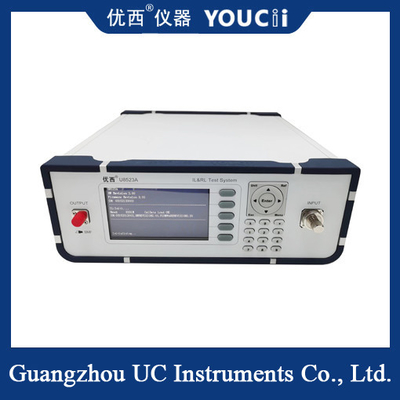
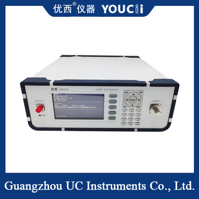
Dual wavelength insertion loss analyzer is a kind of instrument specially used to measure the insertion loss (IL) and return loss (RL) of passive devices (such as connectors, couplers, etc.) in optical fiber communication systems.
Overview
A dual-wavelength insertion loss tester is a high-precision test device capable of measuring insertion loss and return loss at two different wavelengths (usually 1310nm and 1550nm). This instrument plays an important role in the development, production and maintenance of optical fiber communication systems.
Second, the working principle
By inserting a pair of noise sources in the bridge principle, the dual-wavelength plugging-back loss instrument can measure the test circuit under load and no-load conditions. In the test process, the instrument will output a specific frequency and power of the test signal, and then by measuring the incident and reflected power of the test signal, calculate the insertion loss value and return loss value of the measured device at a specific wavelength.
Characteristics
Dual wavelength measurement: It can be measured at 1310nm and 1550nm at two different wavelengths to meet the test needs at different wavelengths.
High precision: Using advanced test technology and algorithm, it can achieve high precision insertion loss and return loss measurement.
Easy operation: With intuitive user interface and simple operation flow, users only need to follow the prompts to complete the test.
Data recording and analysis: It can automatically record test data and provide data analysis functions to help users better understand the performance of the device under test.
Specification
Model # | U8523 |
Sensor Element | InGaAs |
Operation Wavelength Range | 1310 / 1550 nm |
Power Range | + 5 ~ -70 dBm |
Return Loss Range | 0~60 dB |
Application Fiber Type | Standard SM |
Relative Accuracy – Return Loss | ± 0.4 dB |
Absolute Power Accuracy | ± 0.2 dB |
Relative Accuracy – Insertion Loss | < 0.02 dB Typical |
Interface | RS232 |
Power | 100 ~ 240 V AC |
Operation Temperature | 0~ +40℃ |
Storage Temperature | -30~+80℃ |
Recalibration Period | 2 years |
Dimensions | 245mm W×105mm H×320mm D |
Weight | 3.5 kg |
Procedure of use
Test preparation: Make sure the device is properly connected and preheated. Check whether the damage value of measuring line insertion is qualified, and whether the end face is clean.
Return loss to Zero: Connect the beginning end of the marking line to the output interface of the light source, wrap the other end of the marking line with a winding rod, adjust the optical power value of the return loss channel within the specified range, press Zero key until the return loss window displays -00-.
Return loss calibration: loosen the wound marking line, insert the end of the marking line into the optical power meter interface, press the Ref key for calibration.
Return loss measurement: Connect the standard jumper to the device under test, wrap the other end of the device under test 4 to 5 turns, and the value displayed by the instrument is the return loss value of the corresponding wavelength of the device.
Contact Person: Jack Zhou
Tel: 13602867834
Fax: 86-020-82575318